QI_B / Reference structure
Conventional fiber order
A symmetric 16-ply shell over uniform foam B. The half-stack is [0, +45, −45, 90, 0, +45, −45, 90], mirrored through the thickness.
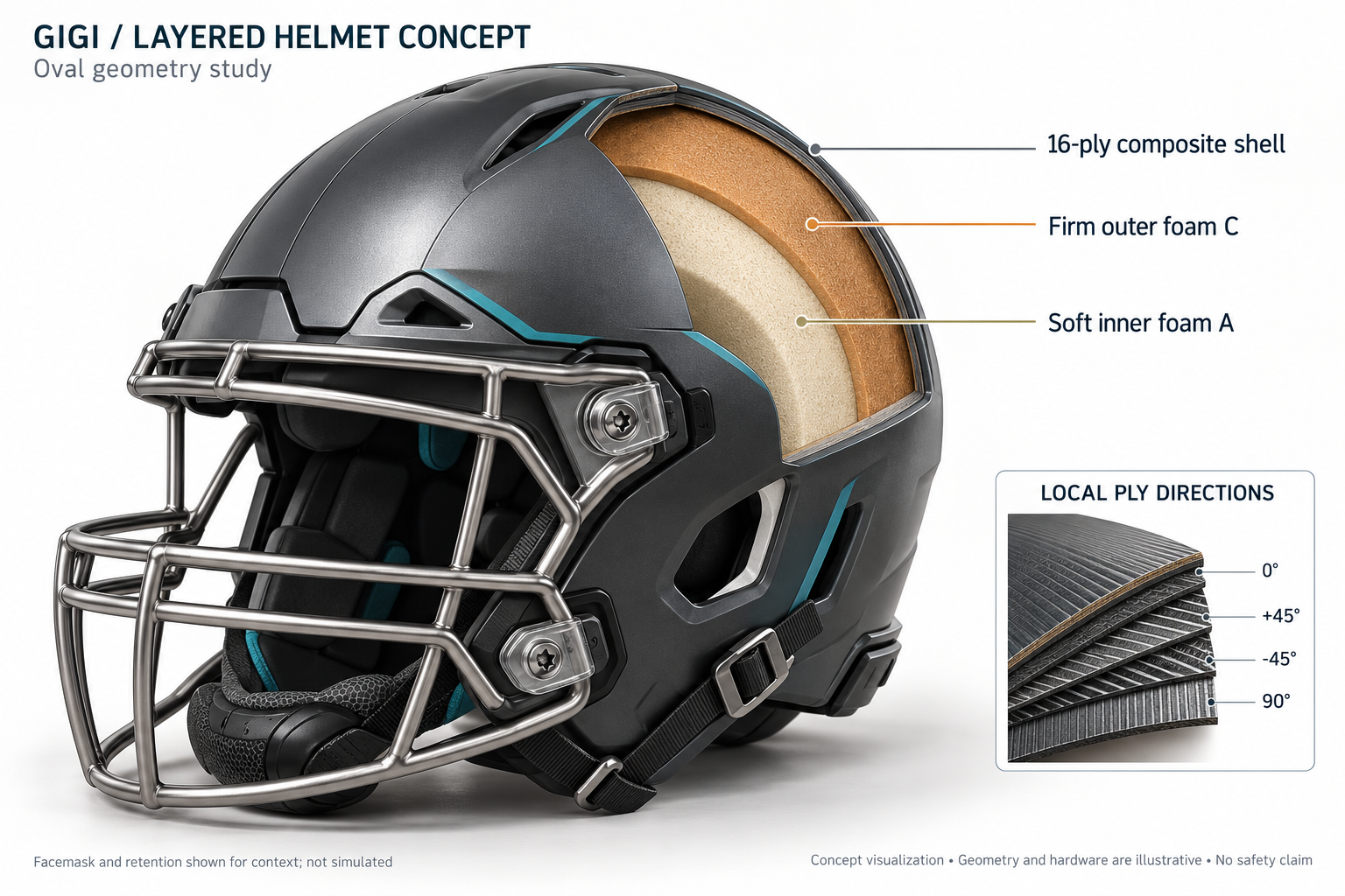
GIGI / Helmet geometry study
How should a helmet’s shape, fibers and cushioning work together?
We compare three shell geometries and three layered structures around the same assumed head. The question is what changes the impact response—and which apparent improvements survive a closer numerical check.
01 / The question
A spherical outer surface changes both contact geometry and the cushioning available at each point. Around a head that is not spherical, the same amount of foam becomes thinner in some places and thicker in others.
This experiment holds the covered head region and target material masses constant. It compares a head-following oval, a spherical cap and an oval that reallocates cushioning toward the crown and sides.
Research scope. This is an unvalidated computational screen. It does not establish a protective helmet, injury reduction or a safety rating.
02 / Geometry
Inspect the actual screening meshes and the local material directions. Changing the angle changes the direction marks, not the measured simulation results.
Actual screening mesh, shown at a common scale. Marks show the local ply material axis; they are not continuous manufactured fiber paths. Gold marks identify elements using the alternate coordinate chart. The face opening is visible; a facemask and chinstrap are not modeled.
Sections share the same scale; the front is to the right. Thicknesses and interfaces come from the model inputs. STL files use millimetres.
03 / Layer architecture
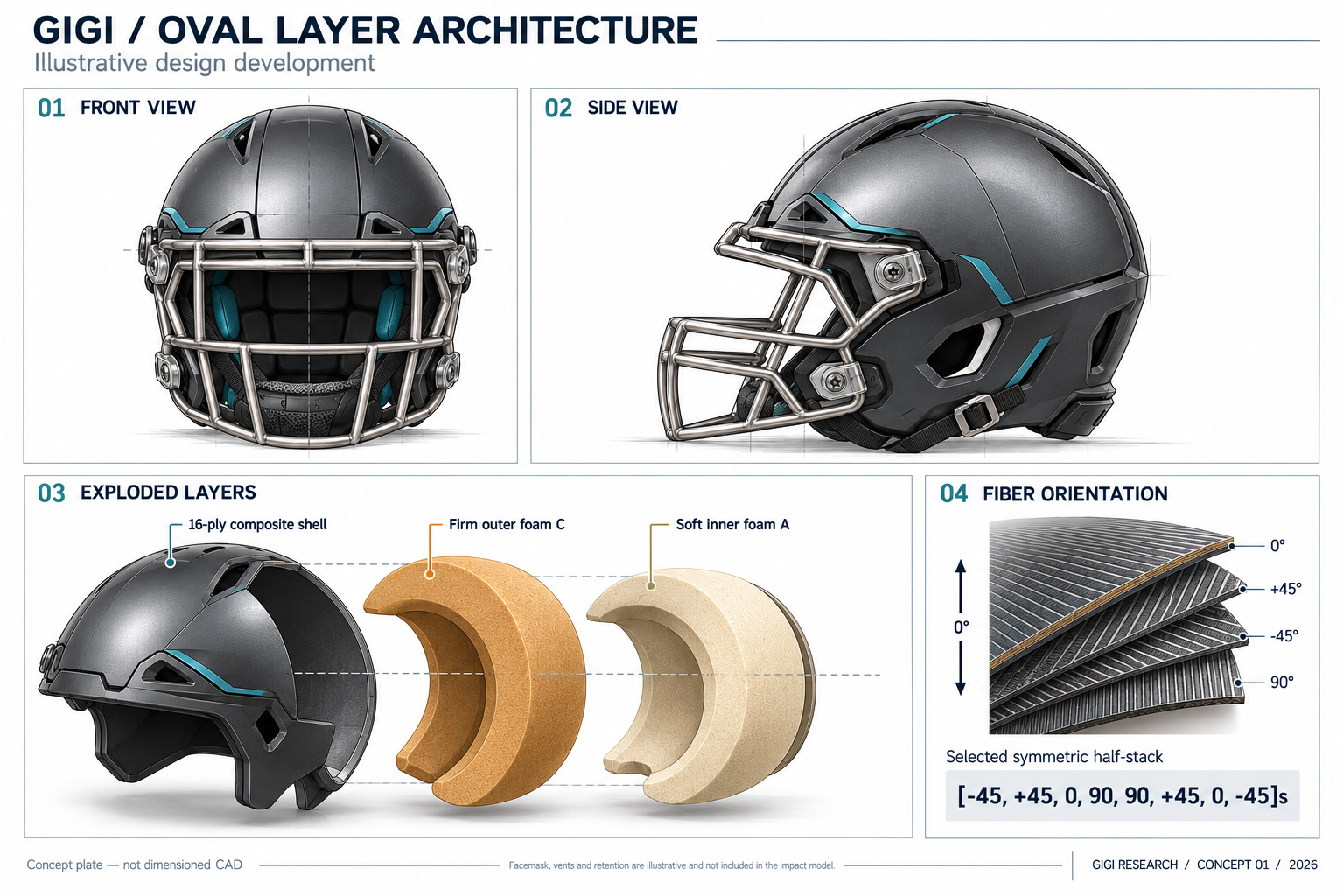
QI_B / Reference structure
A symmetric 16-ply shell over uniform foam B. The half-stack is [0, +45, −45, 90, 0, +45, −45, 90], mirrored through the thickness.
BAL_B / Isolate ply order
The selected half-stack is [−45, +45, 0, 90, 90, +45, 0, −45], mirrored. Angle counts and shell mass are unchanged.
BAL_AC / Change the liner
The selected shell covers soft A foam inside and firm C outside. A occupies 67.84% of liner volume; the interface is solved to match the uniform B liner’s mass.
Angles are local to the shell’s tangent plane. The 0° axis follows projected front-to-back direction, with an alternate coordinate chart near singular projections. These are material axes, not manufacturing paths.
04 / Impact in motion
The same oval, foam and oblique impact. Only the order of the 16 composite plies changes. Play the two simulations together, inspect a ply’s direction, or cut away the shell to see the cushioning.
Loading recorded simulation frames…
Colors show recorded shell stress or computed liner compression. White marks follow the selected ply’s local material axis as the shell deforms. Positions are shown at their actual scale; time is slowed down. The wall remains fixed.
In compression mode, each shell-sized patch shows the largest principal shortening through the four foam elements beneath it. A cutaway exposes the head and liner boundaries; the clipping surface is only a viewing aid.
OpenCourant · 32 × 10 surface mesh · four foam elements through thickness · recorded every 0.25 ms · 3 m/s normal + 3 m/s tangential · assumed friction 0.2. Frames are sampled directly, without invented intermediate load paths. These models omit the facemask and retention hardware shown in the concept renderings.
05 / Measured responses
The spherical cap with reordered fibers and uniform foam leads the initial comparison, with a score 2.6% below the baseline.
The mesh checks change the responses substantially. This initial ordering does not establish a winning helmet. The graded liners also show why linear acceleration and rotation must be assessed together.
| Shape / structure | Linear m/s² | Angular rad/s² | Spin rad/s | Relative score | Cases |
|---|
For each design, take the worst linear acceleration, angular acceleration and angular speed over the five impacts. Divide each by the corresponding worst baseline oval/QI_B metric. The score is the largest of those three ratios. Lower is better under this chosen numerical objective. The score is not an injury probability.
Only designs with all five cases passing the numerical gates enter the initial ranking. Mesh sensitivity is assessed separately.
06 / Impact histories
Compare a design with the baseline under the same impact. Longer frontal histories include restart extensions to finish contact.
07 / Evidence & reproduction
OpenCourant computes the mechanical response. GIGI stores and query-checks the input specifications, estimated surface curvature and measured solver summaries. Surface curvature here is a mesh geometry estimate, not GIGI’s statistical CURVATURE verb.