General arrangement & geometric structure
Read the full arrangement, then separate the exact geometric construction from the engineering inputs that remain unspecified.
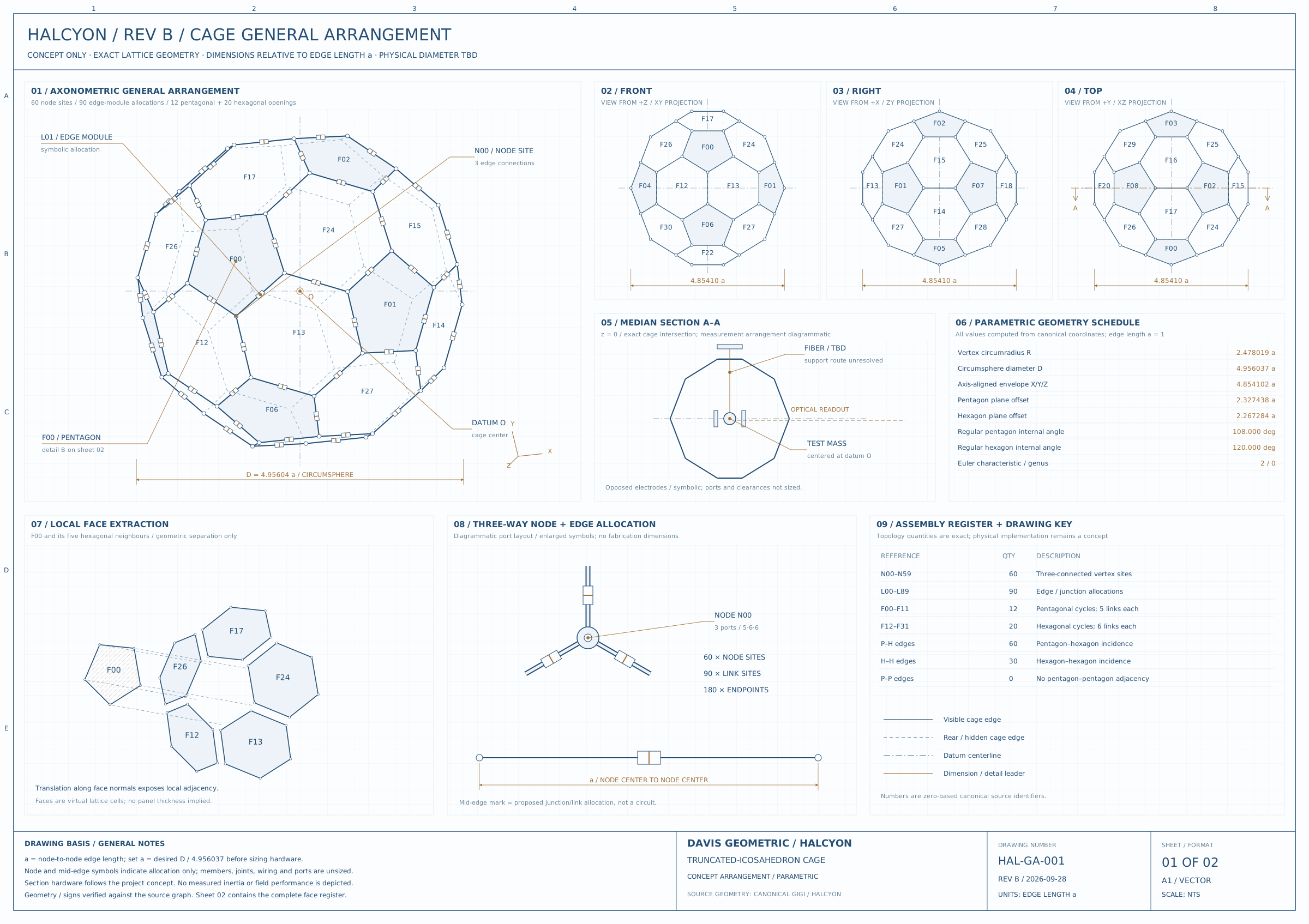
01 / The same structure, seen differently
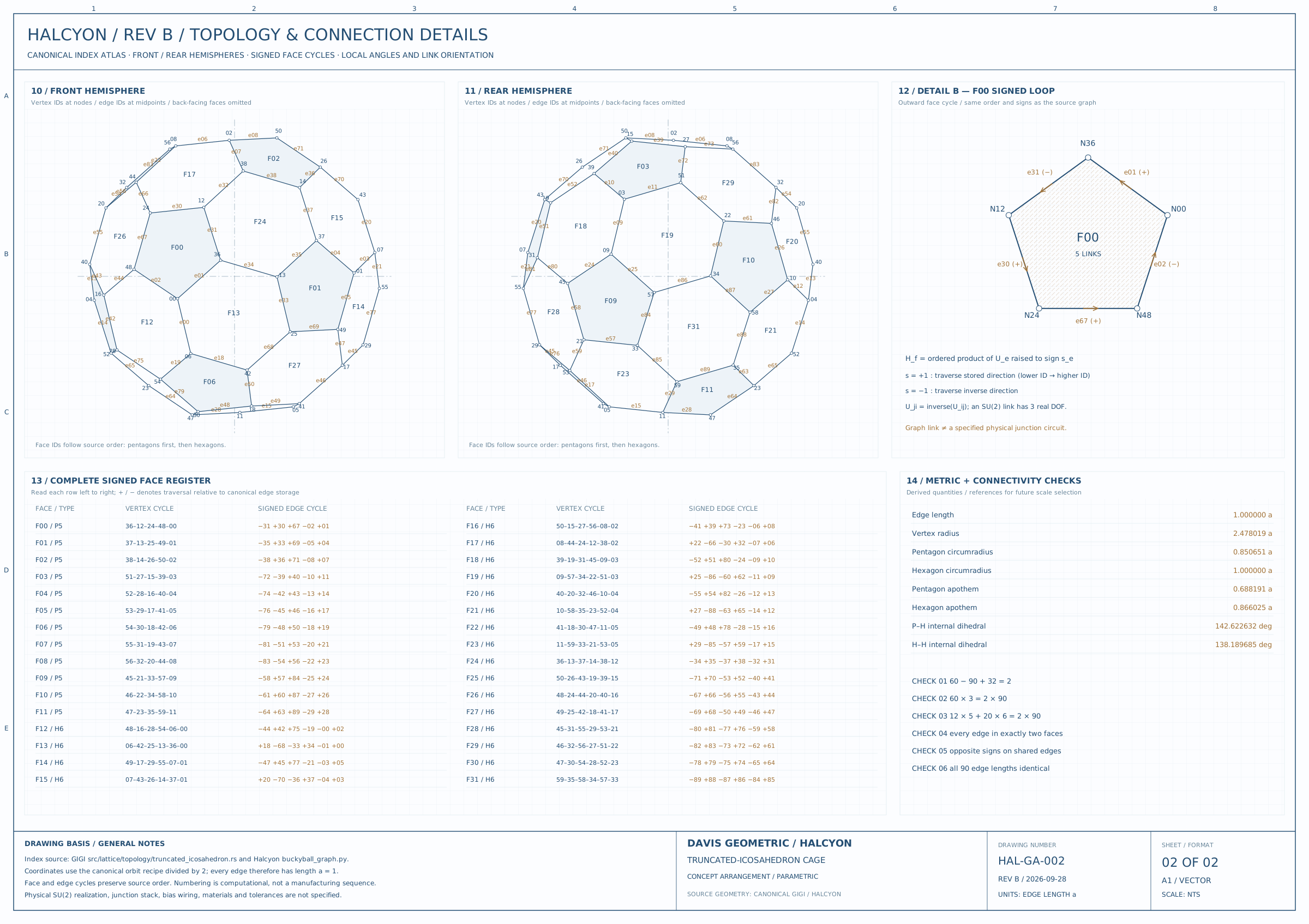
02 / Invariants before engineering
| Object | Count | Interpretation |
|---|---|---|
| Vertices | 60 | Canonical node identifiers |
| Edges | 90 | Undirected adjacencies; each orientation can be tracked |
| Pentagons | 12 | Five-edge face cycles |
| Hexagons | 20 | Six-edge face cycles |
| Euler characteristic | 2 | 60 − 90 + 32 = 2 |
Each vertex has degree three, so the handshaking identity gives 60 × 3 = 2 × 90. Counting the edges around the faces gives 12 × 5 + 20 × 6 = 180 = 2 × 90: each edge is incident to two faces. These consistency checks concern the mathematical surface, not its physical implementation.
Vertex, edge, and face labels let a reader follow the same object across front and rear views. A signed face cycle carries traversal direction; reversing a cycle reverses its orientation. A projection can overlap lines that remain distinct in the three-dimensional construction, so apparent crossings in a view are not additional graph nodes.
03 / How to read the engineering sheet
Applies to HAL-GA-001 (halcyon-revb-general-arrangement) and HAL-GA-002 (halcyon-revb-topology-details).
Established geometry
The coordinates, identifiers, edges and signed face cycles come from the canonical Halcyon/GIGI truncated-icosahedron construction. geometry.json accompanies the release. There are 60 vertices, 90 edges, 12 pentagons and 20 hexagons. The metric schedule is normalized to node-to-node edge length a = 1. Its values are geometric ratios, not physical manufacturing dimensions.
The face register and local adjacency refer to that graph. The median section is the intersection of the geometric cage surface with z = 0. The exploded-face view translates virtual cells to expose adjacency; it is not an assembly sequence for solid panels.
Proposed or diagrammatic elements
The frame cross sections, node symbols, edge-module allocations, attachment shapes, central test mass, suspension, electrodes and optical readout placement illustrate an arrangement. They are not a specified mechanical or electrical apparatus. The source concept mentions suspension, electrostatic excitation and interferometric readout; it does not establish their dimensions or detailed implementation here.
The pentagonal and hexagonal faces are open. No glass panels or enclosure windows are specified. Face fills, hatching and face-plane outlines identify mathematical cells. A vacuum or cryogenic enclosure would require a separate design.
An edge allocation does not imply one physical Josephson junction or one transmon per edge. The later project direction is a multi-mode transmon plaquette network whose physical encoding remains to be characterized. The geometry neither establishes that encoding nor an inertia-modification effect.
Unspecified inputs
Absolute cage size, structural materials, cross sections, joint construction, fabrication tolerances, thermal contraction, strength, enclosure, anchoring, electromagnetic shielding, heat loads, central-mass properties, suspension design, electrode clearances and service access. No depicted dimension should be read as a fabrication instruction.
Release treatment
Rev B remains the drawing revision. The publication-preparation update embeds normal and bold fonts, preserves the A1 vector format and standardizes raster images to 3600 × 2543 pixels. It does not change the source geometry. The release manifest records exact file hashes.
04 / What would be needed for a physical realization
A normalized edge length is not a manufacturing dimension. Turning the geometry into an apparatus requires material choices, joints, tolerances, thermal and mechanical analysis, wiring, and a characterized mapping from physical controls to the proposed mathematical states. The topology and its drawing do not establish that mapping or an inertia-changing effect.
Sources, versions & further reading
Additional diagnostic plates are analytic constructions or descriptive re-plots of the saved record, as labeled. They do not introduce new experimental validation.